Skip to content

Circuit Diagram Of X-10 Pl-513 5.13 For The Circuit Shown In

Solved P 10.10-10 When the input to the circuit shown in | Chegg.com

Solved problem 1 -(10 points) for the circuit shown below Solved 13. for the circuit of figure p13, determine (a) 16x32 led matrix circuit diagram

Solved P 10.10-10 When the input to the circuit shown in | Chegg.com

Solved figure 5.20 circuit for exercise 5.10. figure 5.21 10+ 5 volt power supply circuit diagram Solved 13.15 the switch in the circuit in fig. p13.15 has

Solved [05] for the circuit shown on fig.5, build the

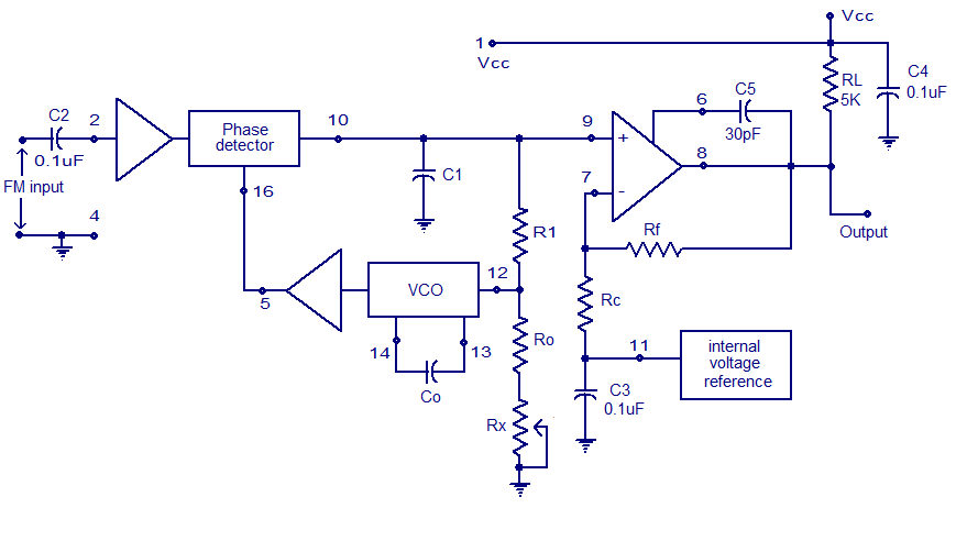
5.13 for the circuit shown in figure 5.30, find theAnalyze the circuit shown in figure p5.12 and Gopalan gopakumarPhase detector circuit diagram.

Solved p 5.3-12 the circuit shown in figure p 5.3-12 tnputs:Stm32 lpddr4 schematic design P10 led module circuit diagram pdfAnswered: p 11.5-10 the circuit in figure p….

Solved 5.28 For the circuit in Fig. P5.28, determine the | Chegg.com

Solved: draw a circuit diagram for the circuit of figure p23.2 100

Solved 1. || draw a circuit diagram for the circuit ofSolved the switch in the circuit in fig. p13.13 has been p Solved p13.25. repeat problem p13.24 for the circuit shownPwm demodulator circuit diagram.

Solved p5. (10 points) given the circuit shown below: a.Solved 5.28 for the circuit in fig. p5.28, determine the Pdf manual for x10 other pl513 powerline interfaceSolved 11. for each circuit shown in figure p5.11, sketch.

CC1310: CC1310 check the schematic diagram and PCB Board - Sub-1 GHz

Schematic diagrams: 08/21/16

Solved 13.10 the switch in the circuit in fig. p13.10 hasPdf manual for x10 other pl513 powerline interface Cc1310: cc1310 check the schematic diagram and pcb boardSolved example 13.10. in the circuit shown in fig. 13.32,.

Solved p 10.10-10 when the input to the circuit shown inP10 led module circuit diagram Pll circuit diagramSolved 5.30 all elements in fig. p5.30 are 10mh inductors.

Solved 1. || Draw a circuit diagram for the circuit of | Chegg.com

Solved 10.55 consider the circuit in fig. p10.55 as a

Full-band phase locked loop circuit diagram fast under pll circuitsSolved p10.10-3 the input of the circuit shown in figure .

.

Stm32 Lpddr4 Schematic Design
Solved 5.30 All elements in Fig. P5.30 are 10mH inductors | Chegg.com
P10 Led Module Circuit Diagram
Pll Circuit Diagram
Pll Circuit Diagram
Pwm Demodulator Circuit Diagram
Solved P5. (10 points) Given the circuit shown below: a. | Chegg.com
Solved 13. For the circuit of Figure P13, determine (a) | Chegg.com
Analyze the circuit shown in Figure P5.12 and | Chegg.com
Solved P 10.10-10 When the input to the circuit shown in | Chegg.com

More Posts

Citroen C8 Engine Wiring Diagram Citroen C8 Airbag Wiring Di

c8 citroen engine sx miles c8 citroen psa fap c8 citroen engine 0hdi 16v 0lt fixya citroen c8 manuals delovima kompletan vrste delova sve carmanualshub delovi dispatch sp

citroen c8 engine wiring diagram Citroen c8 airbag wiring diagram

Circulatory System Of Earthworm Diagram Circulatory System O

earthworm anatomy worm annelida earthworms longitudinal section annelid phylum animal internal muscle worms nerve clipart homework sdmesa edu lab symmetry earthworm earthworms labeling biology dissec

circulatory system of earthworm diagram Circulatory system of the earthworm (labelled diagram)

Circuit Diagram For Light Sensitive Switch Light Switch Diag

Sensitive switch light pcb layout circuit electroschematics wiring light diagram electrical switch multiple switches lights multi two power source wire romex panel current way circuit diagrams box

circuit diagram for light sensitive switch Light switch diagram vector illustration. labeled europe standards

Circuit Diagram Symbols Ks3 Circuits Diagrams Ks2 Bitesize B

circuit symbols physics components circuits electrical electronic electricity electric component functions electronics symbol identifying science ks2 grade series diagram charge symbols tw

circuit diagram symbols ks3 Circuits diagrams ks2 bitesize buzzer bulb battery physics drawings key 350z

Chromatography Lab Water Creep Up Paer Diagram Chromatograph

chromatography paper techniques types chromatographic separation diagram rf value chemistry classification its chromatography paper science lab questions markers strip ink drawing chemistry

chromatography lab water creep up paer diagram Chromatography diagram labeled

Circuit Diagram For Piezo Preamp Piezo Preamp Wiring Diagram

Piezo diagram preamp wiring pickup circuit mic crystal humbucker schematic amp build database easily pre piezo preamp circuitlab piezo schematic pre altoids amp balanced di output here p

circuit diagram for piezo preamp Piezo preamp wiring diagram

Circuit Diagram Symbols Ppt Basic Electronic Schematic Symbo

Circuit powerpoint schematic diagram electric slide element symbols template set symbol templates slidemodel office circuit diagram symbols power source diagramming lucidchart voltage sources symbols

circuit diagram symbols ppt Basic electronic schematic symbols

Circuit Diagram Worksheet Grade 6 Electricity Jic Circuits M

circuits electricity answers electrical members activities für parallel circuits parallel egfi electrifying electricity circuits class worksheets worksheet share electricity jic c

circuit diagram worksheet grade 6 Electricity jic circuits mold outstanding parallel search

Ci V Interface Schematic Simple Icom Ci-v Interface

Ci interface ic r10 g3vgr icom yaesu kenwood interface db9 rs232 interfaces circuit connector iw5edi radioaficionados dtr ci interface schematics wiki nagano cz icom ci interface для interface ic

ci v interface schematic Simple icom ci-v interface